How to Build a Better Gearbox Motor Conveyor Idlers
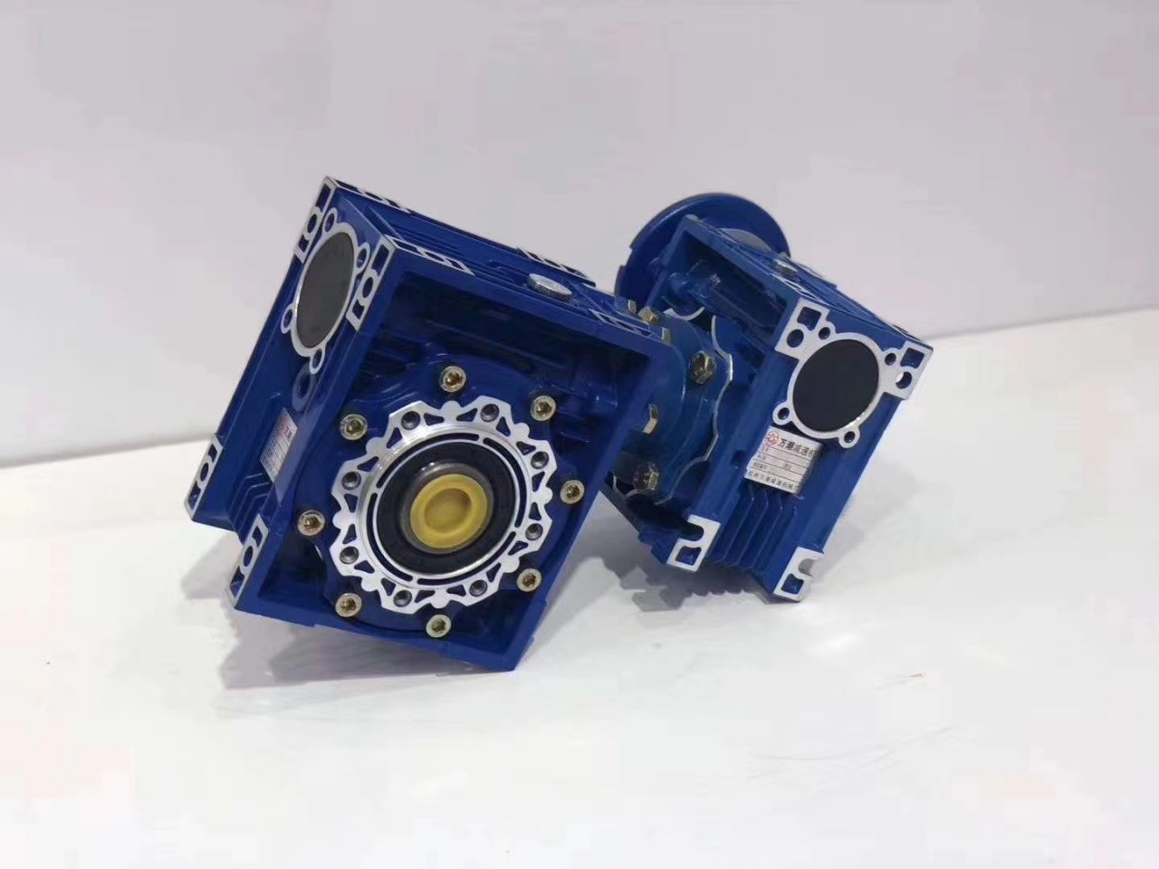
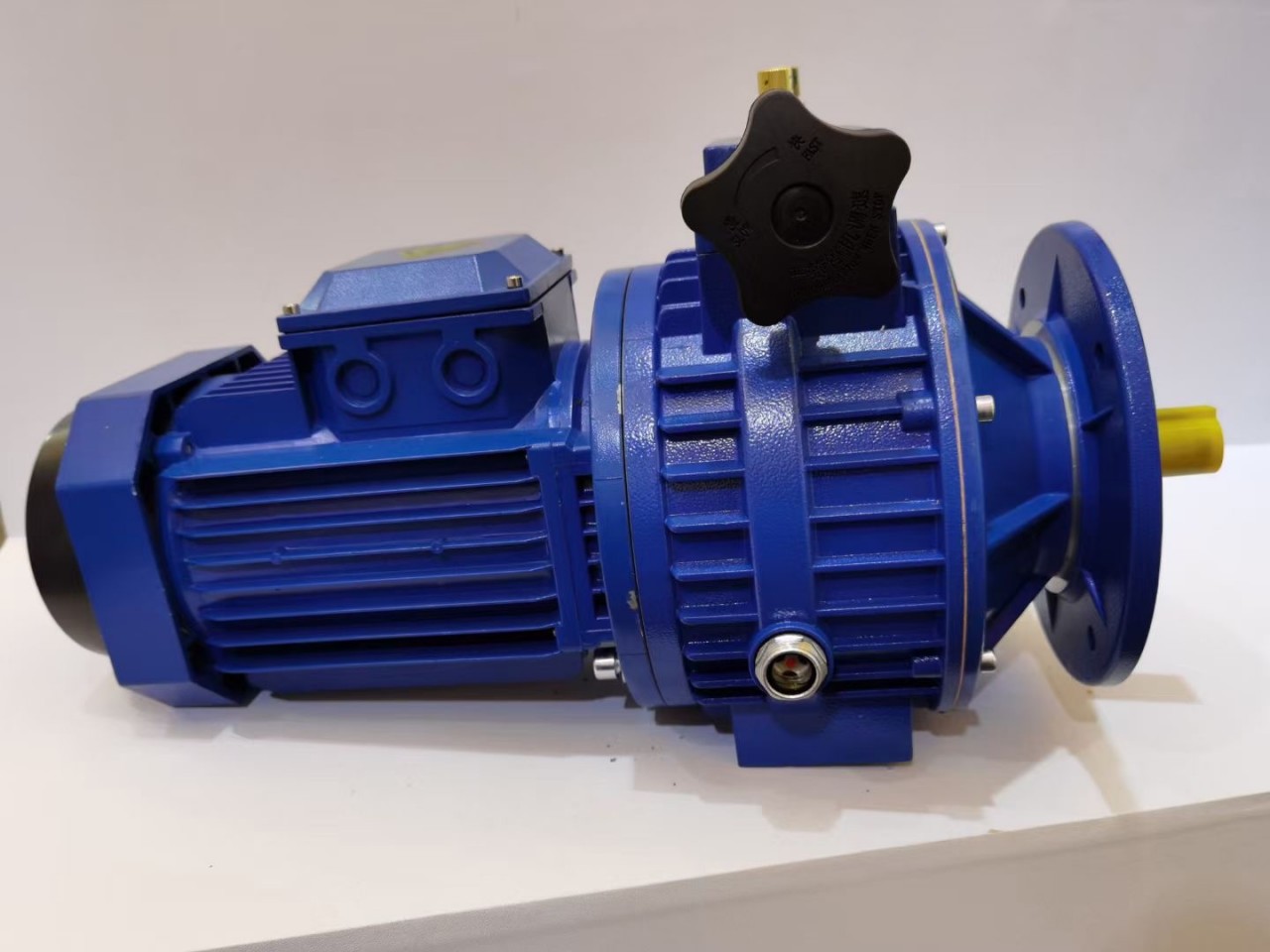
What does a gearbox do and why would someone need one? Gearboxes, also known as enclosed gear drives or speed reducers, are mechanical drive components that can control a load at a reduced fixed ratio of the motor speed. The output torque is also increased by the same ratio, while the horsepower remains the same. Typical applications are used with electric motors for reducing the output speed and increasing torque. Gearboxes are used on conveyors, packaging machines, rotary tables and more!
Keep in mind: Loads play a huge factor in selection as well. You may only have light uniform loads to move, or you may have moderate loads. Heavy loads can create shock to the mechanical driveline causing more stress and wear.
How do I select the correct gearbox? You will need to look at: Usage, Power, Environment and Mounting. AutomationDirect has a great selection guide that can be found on our website here:
1) Determine the torque and speed required for the load.
2) Determine the overall speed ratio of motor speed to load speed.
3) Determine the gearbox ratio as well as any reduction outside the gearbox (pulleys, gears, etc.).
4) Determine the applicable service factor and overhung load K factor.
5) Determine the gearbox real output torque required, and select a gearbox with a higher Maximum Thermal output Torque rating .
6) Determine the gearbox design output torque required and select a gearbox with a higher Maximum Mechanical Output Torque rating.
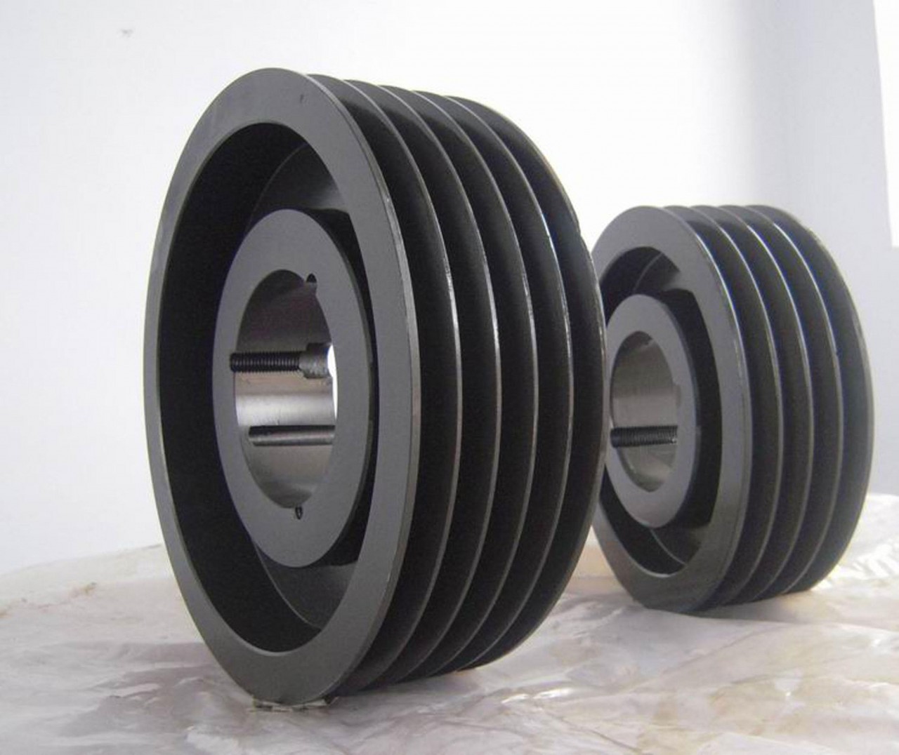
7) Determine the required sizes of pulleys, gears, etc., and determine the overhung load force. Select a gearbox with a higher Overhung Load rating.
8) Confirm that the selected gearbox meets the applicable system requirements.
9) Select a compatible motor.
One of the most overlooked selection criteria is frequency of starting and stopping and what loads the gearbox will be controlling. Stopping and starting a gearbox increases stress and wear. If your application runs continuous without stopping and starting, then a lighter duty gearbox may work for your application.
For single idler scales we consider a minimum of 2 idler before and 2 idlers after the beltscale. For multi-idler scales we consider a minimum of 3 idler before and 3 idlers after the beltscale. Idler alignment means that the target idlers are all the same make, model and shape and that they are all on the same plane. This means if we were to place a long straight edge at any common point on the idlers that they would all come in contact with it. It is not always practical to use a straight edge, so the easiest method to achieve a detailed idler alignment is the string line method.
During the alignment process is an excellent time to ensure that the idler spacing is all the same for a minimum of 2 spaces before and after the beltscale and that all of the idlers are parallel to one another and square to the frame of the conveyor. The tolerance value for the vertical alignment is very tight because the deflection of a loadcell is very small.
Under here we have Bearings, Shaft. Gear box, Roller Chain and we have inspection sections at each side. The inspection section at this end, has a hole in it and that is where we put the lubricator. The lubricator brush fits right in there. A typical drive unit here these drive dogs grab the horizontal bearing and push this chain, pull this chain through so there's a tight side, there's a side with the highest tension in the whole system and on the opposite side, it has the lowest tension on the whole system.
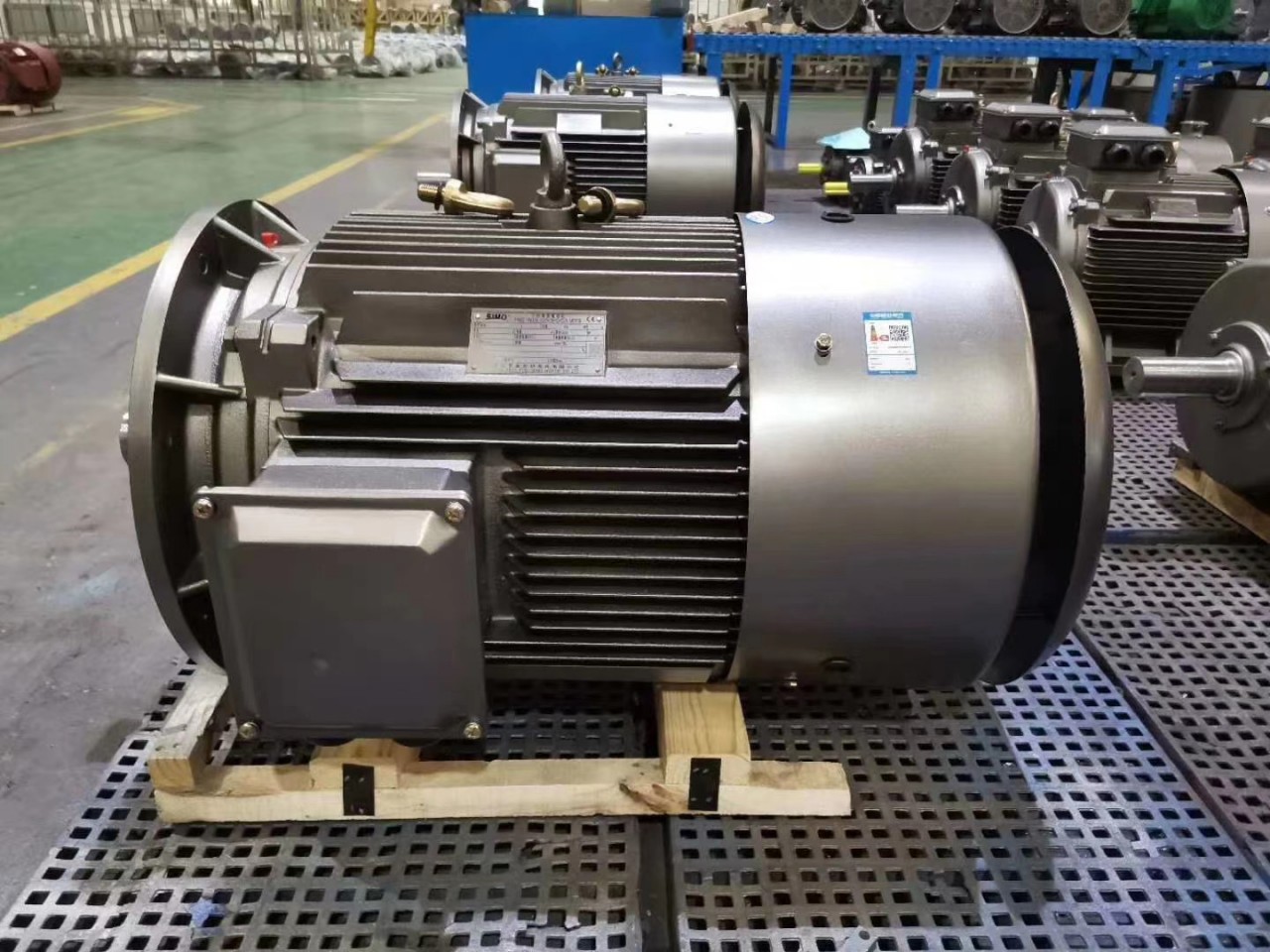
The next most common problem on our drive unit would be basically, gearbox and motor one or the other so your system's gone down and you need to figure out what's going on.
Related Posts
By accepting you will be accessing a service provided by a third-party external to https://www.guomaodrive.com/


Comments