Gear Lubricants knowledge introduction
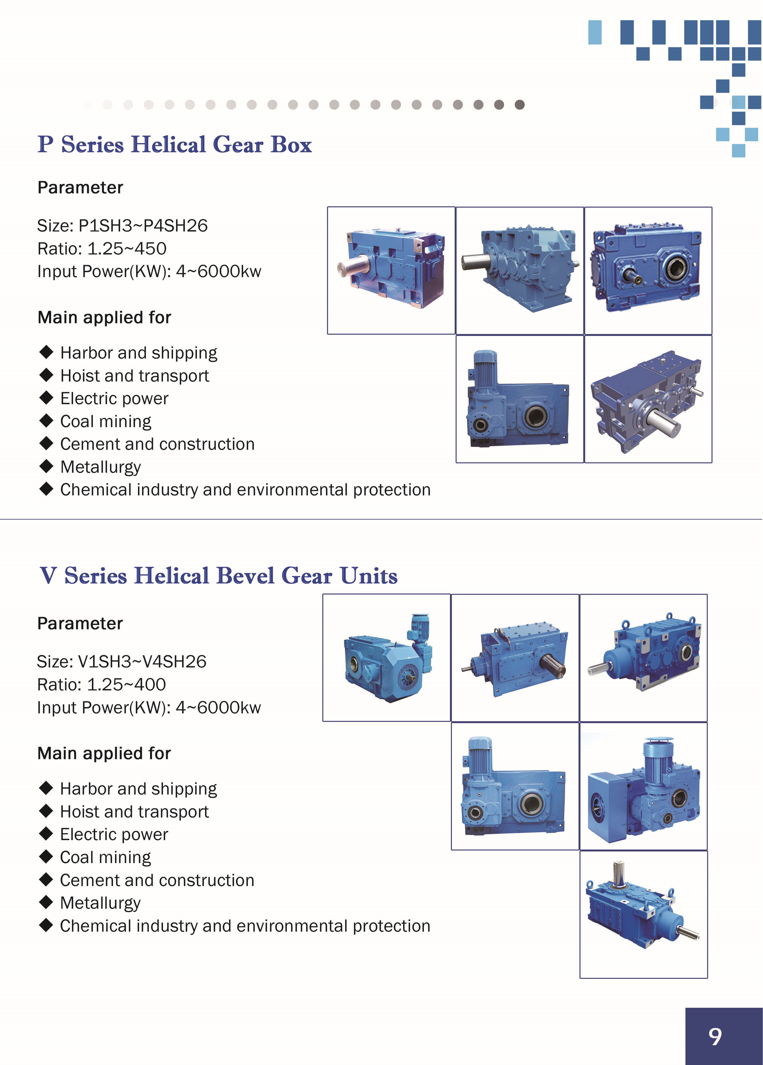
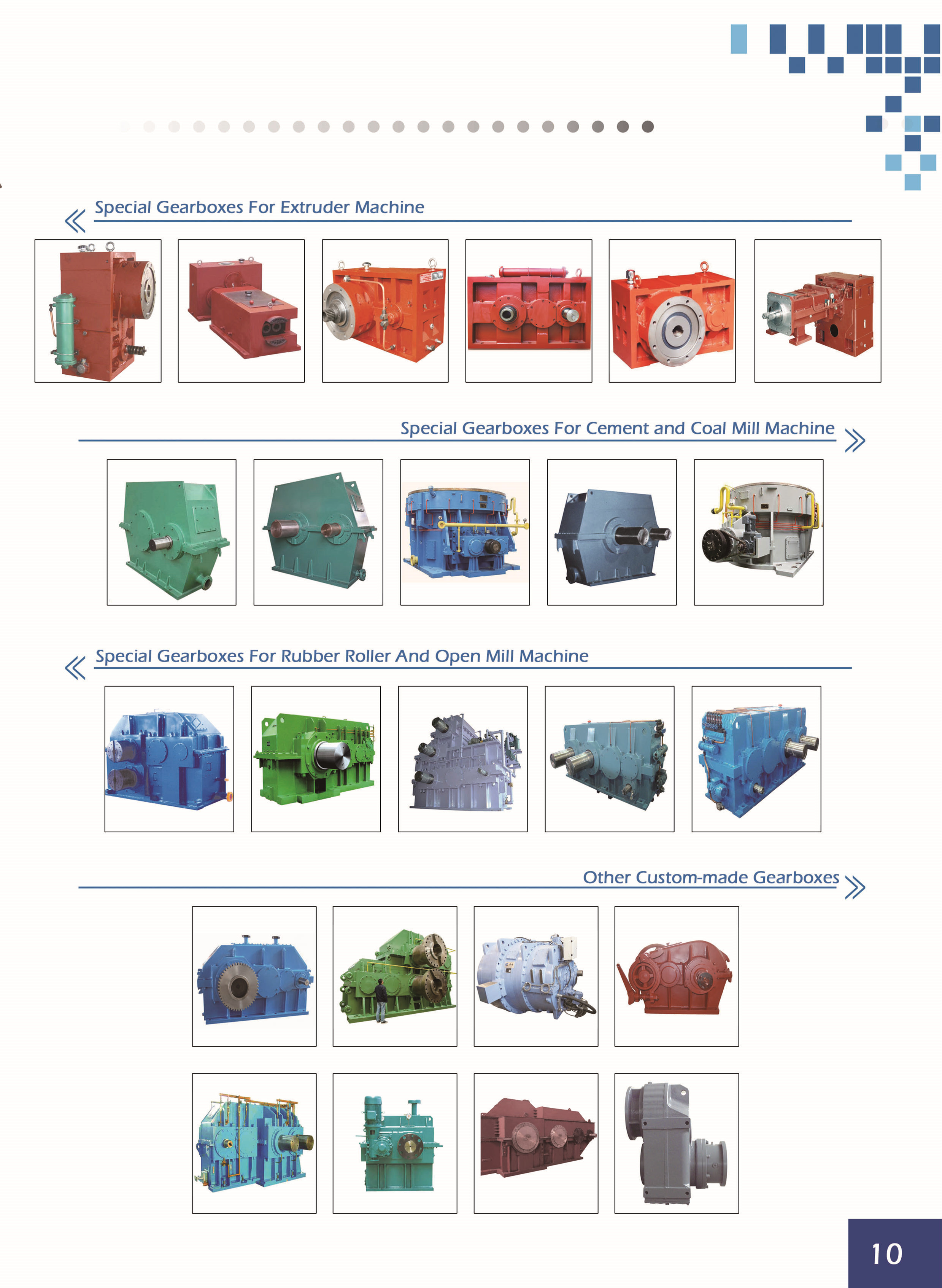
Bevel gear, helical gears ,cylindrical gear (SPUR GEARS),spiral bevel gear,worm snail bar (WORM & WORM WHEELS),reducer (SPEED REDUCERS) / gearbox, etc.
Gear Lubricants referred gear oil, which is mainly used to lubricate the various mechanical gears.Gear oils and engine lubricants, as also the group consisting of mineral oil type (or synthetic) base oil and additives corresponding
A. Gear oils and gear oil can be divided into two categories industrial gear oils.
Gear oil Introduction
Vehicle gear oil is mainly used in automobile, engineering machinery transmission, steering, front and rear drive axle. Gearbox, universal joints needle bearings and other parts, but also for tanks, ships, and the corresponding load and working conditions
Gear member. Industrial gear oil is mainly used to open under various load conditions, semi-open, closed and Worm gear.
First, the gear oil working conditions and its role:
A variety of mechanical transmission gear mechanism, according to its different axes of the mutual positional relationship can be divided into parallel Shaft drive, intersect and cross shaft drive shaft drive. According to the shape of each type of transmission in different gears and teeth have different
Transmission methods, such as parallel shaft drive spur gears, helical gears, spur gears herringbone; Intersecting axis drive straight bevel gears, helical bevel gears, spiral bevel gears; staggered shaft drive has hyperbolic
Gears, worm, helical gear.
1. gear characteristics and working conditions of gear oil
(1) high-efficiency gear, generally cylindrical gear transmission efficiency up to 98%, compared with the bearing, gear
Equivalent curve radius wheel is small, wedge poor conditions.
(2) gear tooth is in line contact with the teeth, and therefore, the contact area, contact pressure units high.
General Automotive gear unit contact pressure up 2000-3000MPa, while higher hypoid gear up to
3000 a 4000MPa.
(3) gear not only line contact, there is sliding contact, especially between the hypoid gear, tooth
They have a higher relative sliding velocity, generally up to about 8m / o. This is in the high speed high load conditions, will
Thin film and even a partial rupture, leading to increased friction and wear, and even cause abrasions and bite.
(4) gear oil operating temperature is generally lower than the internal combustion engine oil, in large part with the ambient temperature changes
Changes, vehicle gear oil temperature is generally not higher than 100'C. Modern cars use hypoid gear, its axis
Line a large offset high gear side will ask the vehicle speed is high relative sliding speed, the oil temperature reaches
160'C a 180'C.
2. The role of gear oil in the gear
(1) reduce wear gears and other moving parts, prolong gear life.
(2) reduce friction, reduce power loss.
(3) dispersing the heat, since a certain cooling effect.
(4) to prevent corrosion and rust.
(5) reduces operating noise and reduce vibration and shock effect between gears.
(6) washing the dirt, especially among rushed tooth surface dirt, reducing wear and tear.
Second, the gear oil properties:
The purpose of the use of different gear oil, conditions of use varies widely with its performance as follows Claim:
1. Good oil and extreme pressure anti-wear
Oily refers gear oil can effectively adsorb oil film lubrication between moving surfaces, have lower
The nature of the low friction. Abrasion resistance refers to the oil held in the oil film between the moving parts, can effectively prevent the metal
Direct contact between the ability to add some of the active substance with polar molecules in the gear oil can improve its oil
Sex, oxides of these oily agents polar end and the metal surface adsorption occurs, to form a strong oily
Membranes, polar end oiliness agent may also form a metal soap type lubricant film and the metal oxide surface, to strengthen the tooth
Wheel lubrication oil, to prevent direct contact tooth surface, to reduce friction, thereby reducing wear. Some of the gear transmission
Move, often working under extreme pressure lubrication harsh conditions, the pressure, sliding speed and local temperatures
High, which requires adding extreme pressure gear oil additives. Extreme pressure additives are typically chemically active
Parathion, parathion chlorine-type or oil-soluble zinc compounds, these additives at high temperature and pressure conditions and extreme metal tooth shape
To iron chlorine, sulfur, phosphorus compounds or complexes, to form a high melting point of the inorganic film, this film has a very
Extreme pressure resistance properties, but also have the role of resistance to shock loading, can be effectively prevented under high load conditions
Tooth surface scratches and bite.
2. Good viscosity-temperature characteristics
All kinds of lubricating oil viscosity decreases with increasing temperature, the smaller the proportion of decline, its viscosity-temperature performance
The better. Especially in the automotive and construction machinery gear oil operating temperature range varies greatly, therefore, hope that the gear oil
Viscosity change with temperature as low as possible. Gear oil viscosity-temperature characteristics as well, when you start the viscosity is too large,
Easy to start, and run to a temperature high limit viscosity is too small. Viscosity gear oil is also important usability
One great energy, viscosity influence on the formation of the oil film. In general, high viscosity gear oil can effectively prevent the gear
And bearing damage, reduce noise and minimize leakage mechanical operation; low-viscosity oil to improve the operating efficiency of machinery plus
Transmission is stronger cooling and cleaning action and the oil has an advantage. In order to reduce fuel consumption, foreign introduced hair
Engine oil, gear oil of low viscosity. The advantages of low viscosity gear oil agitating resistance is small gear teeth, and
Has good low temperature fluidity, at low temperature to ensure lubrication. In recent years, the country has produced some of the low viscosity
Degree of gear oil, in order to change its lubricating properties and Poor's added some pleiotropic additives which reduce power loss
Is very favorable. Of course, in the use of its body, to strengthen the gear box sealed to prevent gear oil
Leakage.
3. Good low temperature fluidity
Automotive gear oil requirements at low temperatures can maintain the necessary fluidity, if the gear oil at a low temperature strip
Lower member wax precipitation, a sharp rise in viscosity, it can not ensure effective lubrication, low temperature start torque is increased, so that
Was an increase in fuel consumption.
Tests showed low apparent viscosity gear oil lubrication reliability of the vehicle starting an important shadow
Ring. Inflows driving bevel gear axle vehicles after the start, rear axle (front axle) gear oil is Jijian to upper rear axle housing
Cheng, when asked if this is too long, there may be due to lack of oil bearing burned. Therefore, the requirements of the vehicle so that the gear oil
With the apparent viscosity at low temperature of not more than 1.5X100000mPa.s. Vehicle gear oil specifications apparent bid out
1.5X100000mpa.s temperature viscosity when it determines the gear oil for the minimum temperature, the election
One important basis for gear oil used. In order to be able to adapt to the requirements of gear oil under low temperature in winter conditions, tooth
Round to join the oil pour point depressants, to improve its low temperature fluidity.
4. Good thermal oxidation stability
Gear oil under severe operating conditions, in air, water and metal catalyzed oxidation rate
Accelerate, the viscosity increases, resulting insolubles and corrosive substances and resin and asphaltene, nature deterioration and easy milk
Technology and produce foam, so Huanyouzhouqi shortened. To retard oxidation gear oils, typically added phenol in oil,
Amine or curing type antioxidant additives.
5. Good rust and corrosion
Rust resistance refers to the gear oil to protect gear from corrosion, thus ensuring performance and prolong gear so
Life. Gear during operation, the moisture in the air condenses into water gearbox, thus requiring gear
Oil should have good rust resistance. In order to enhance rust resistance gear oil, generally added salt or salts of fatty acids
And other anti-corrosion additives. Plus there is extreme pressure gear oil additives, extreme pressure additives due to sulphide, sulfur on copper
Easy to produce corrosion, therefore, to join in the gear oil in anti-corrosion additives, which can form on the metal surface protection
Protective film to prevent corrosion of metal corrosive substances.
6. Good anti-foam
Gear oils requires a good anti-foam to ensure under operating conditions, intense stir in gear
Mixing process produces less foam and easy to disappear.